Abstract
With rapid advances in high-speed communication and computation, augmented reality (AR) and virtual reality (VR) are emerging as next-generation display platforms for deeper human-digital interactions. Nonetheless, to simultaneously match the exceptional performance of human vision and keep the near-eye display module compact and lightweight imposes unprecedented challenges on optical engineering. Fortunately, recent progress in holographic optical elements (HOEs) and lithography-enabled devices provide innovative ways to tackle these obstacles in AR and VR that are otherwise difficult with traditional optics. In this review, we begin with introducing the basic structures of AR and VR headsets, and then describing the operation principles of various HOEs and lithography-enabled devices. Their properties are analyzed in detail, including strong selectivity on wavelength and incident angle, and multiplexing ability of volume HOEs, polarization dependency and active switching of liquid crystal HOEs, device fabrication, and properties of micro-LEDs (light-emitting diodes), and large design freedoms of metasurfaces. Afterwards, we discuss how these devices help enhance the AR and VR performance, with detailed description and analysis of some state-of-the-art architectures. Finally, we cast a perspective on potential developments and research directions of these photonic devices for future AR and VR displays.
Metasurface wavefront control for high-performance user-natural augmented reality waveguide glasses
ArticleOpen access06 April 2022
Advanced liquid crystal devices for augmented reality and virtual reality displays: principles and applications
ArticleOpen access30 May 2022
Microdisplay technologies in augmented reality and virtual reality headsets
Article13 August 2025
Explore related subjects
Discover the latest articles and news in related subjects.
Introduction
Recent advances in high-speed communication and miniature mobile computing platforms have escalated a strong demand for deeper human-digital interactions beyond traditional flat panel displays. Augmented reality (AR) and virtual reality (VR) headsets1, 2 are emerging as next-generation interactive displays with the ability to provide vivid three-dimensional (3D) visual experiences. Their useful applications include education, healthcare, engineering, and gaming, just to name a few3, 4, 5. VR embraces a total immersive experience, while AR promotes the interaction between user, digital contents, and real world, therefore displaying virtual images while remaining see-through capability. In terms of display performance, AR and VR face several common challenges to satisfy demanding human vision requirements, including field of view (FoV), eyebox, angular resolution, dynamic range, and correct depth cue, etc. Another pressing demand, although not directly related to optical performance, is ergonomics. To provide a user-friendly wearing experience, AR and VR should be lightweight and ideally have a compact, glasses-like form factor. The above-mentioned requirements, nonetheless, often entail several tradeoff relations with one another, which makes the design of high-performance AR/VR glasses/headsets particularly challenging.
In the 1990s, AR/VR experienced the first boom, which quickly subsided due to the lack of eligible hardware and digital content6. Over the past decade, the concept of immersive displays was revisited and received a new round of excitement. Emerging technologies like holography and lithography have greatly reshaped the AR/VR display systems. In this article, we firstly review the basic requirements of AR/VR displays and their associated challenges. Then, we briefly describe the properties of two emerging technologies: holographic optical elements (HOEs) and lithography-based devices (Fig. 1). Next, we separately introduce VR and AR systems because of their different device structures and requirements. For the immersive VR system, the major challenges and how these emerging technologies help mitigate the problems will be discussed. For the see-through AR system, we firstly review the present status of light engines and introduce some architectures for the optical combiners. Performance summaries on microdisplay light engines and optical combiners will be provided, that serve as a comprehensive overview of the current AR display systems.
Fig. 1: Schematic of some emerging optical technologies applied in AR/VR.
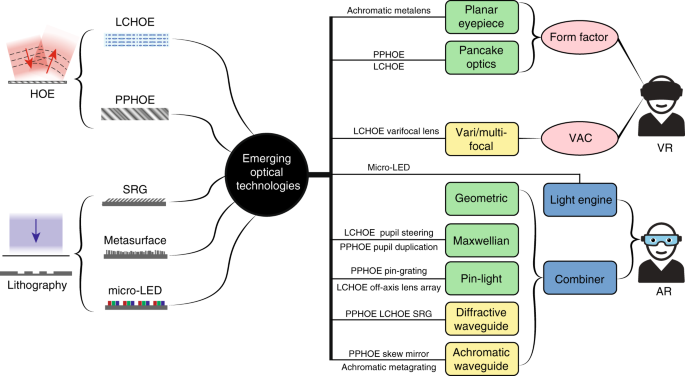
The left side illustrates HOEs and lithography-based devices. The right side shows the challenges in VR and architectures in AR, and how the emerging technologies can be applied
Key parameters of AR and VR displays
AR and VR displays face several common challenges to satisfy the demanding human vision requirements, such as FoV, eyebox, angular resolution, dynamic range, and correct depth cue, etc. These requirements often exhibit tradeoffs with one another. Before diving into detailed relations, it is beneficial to review the basic definitions of the above-mentioned display parameters.
Definition of parameters
Taking a VR system (Fig. 2a) as an example. The light emitting from the display module is projected to a FoV, which can be translated to the size of the image perceived by the viewer. For reference, human vision’s horizontal FoV can be as large as 160° for monocular vision and 120° for overlapped binocular vision6. The intersection area of ray bundles forms the exit pupil, which is usually correlated with another parameter called eyebox. The eyebox defines the region within which the whole image FoV can be viewed without vignetting. It therefore generally manifests a 3D geometry7, whose volume is strongly dependent on the exit pupil size. A larger eyebox offers more tolerance to accommodate the user’s diversified interpupillary distance (IPD) and wiggling of headset when in use. Angular resolution is defined by dividing the total resolution of the display panel by FoV, which measures the sharpness of a perceived image. For reference, a human visual acuity of 20/20 amounts to 1 arcmin angular resolution, or 60 pixels per degree (PPD), which is considered as a common goal for AR and VR displays. Another important feature of a 3D display is depth cue. Depth cue can be induced by displaying two separate images to the left eye and the right eye, which forms the vergence cue. But the fixed depth of the displayed image often mismatches with the actual depth of the intended 3D image, which leads to incorrect accommodation cues. This mismatch causes the so-called vergence-accommodation conflict (VAC), which will be discussed in detail later. One important observation is that the VAC issue may be more serious in AR than VR, because the image in an AR display is directly superimposed onto the real-world with correct depth cues. The image contrast is dependent on the display panel and stray light. To achieve a high dynamic range, the display panel should exhibit high brightness, low dark level, and more than 10-bits of gray levels. Nowadays, the display brightness of a typical VR headset is about 150–200 cd/m2 (or nits).
Fig. 2: Illustration of display parameters.
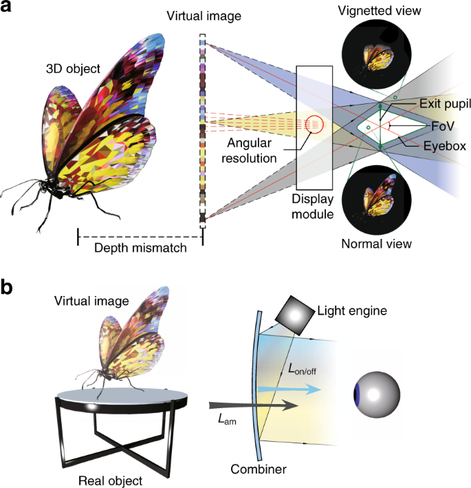
a Schematic of a VR display defining FoV, exit pupil, eyebox, angular resolution, and accommodation cue mismatch. b Sketch of an AR display illustrating ACR
Figure 2b depicts a generic structure of an AR display. The definition of above parameters remains the same. One major difference is the influence of ambient light on the image contrast. For a see-through AR display, ambient contrast ratio (ACR)8 is commonly used to quantify the image contrast:
(1)
where L on ( L off) represents the on (off)-state luminance (unit: nit), L am is the ambient luminance, and T is the see-through transmittance. In general, ambient light is measured in illuminance (lux). For the convenience of comparison, we convert illuminance to luminance by dividing a factor of π, assuming the emission profile is Lambertian. In a normal living room, the illuminance is about 100 lux (i.e., L am ≈ 30 nits), while in a typical office lighting condition, L am ≈ 150 nits. For outdoors, on an overcast day, L am ≈ 300 nits, and L am ≈ 3000 nits on a sunny day. For AR displays, a minimum ACR should be 3:1 for recognizable images, 5:1 for adequate readability, and ≥10:1 for outstanding readability. To make a simple estimate without considering all the optical losses, to achieve ACR = 10:1 in a sunny day (~3000 nits), the display needs to deliver a brightness of at least 30,000 nits. This imposes big challenges in finding a high brightness microdisplay and designing a low loss optical combiner.
Tradeoffs and potential solutions
Next, let us briefly review the tradeoff relations mentioned earlier. To begin with, a larger FoV leads to a lower angular resolution for a given display resolution. In theory, to overcome this tradeoff only requires a high-resolution-display source, along with high-quality optics to support the corresponding modulation transfer function (MTF). To attain 60 PPD across 100° FoV requires a 6K resolution for each eye. This may be realizable in VR headsets because a large display panel, say 2–3 inches, can still accommodate a high resolution with acceptable manufacture cost. However, for a glasses-like wearable AR display, the conflict between small display size and the high solution becomes obvious as further shrinking the pixel size of a microdisplay is challenging.
To circumvent this issue, the concept of the foveated display is proposed9, 10, 11, 12, 13. The idea is based on that the human eye only has high visual acuity in the central fovea region, which accounts for about 10° FoV. If the high-resolution image is only projected to fovea while the peripheral image remains low resolution, then a microdisplay with 2K resolution can satisfy the need. Regarding the implementation method of foveated display, a straightforward way is to optically combine two display sources9, 10, 11: one for foveal and one for peripheral FoV. This approach can be regarded as spatial multiplexing of displays. Alternatively, time-multiplexing can also be adopted, by temporally changing the optical path to produce different magnification factors for the corresponding FoV12. Finally, another approach without multiplexing is to use a specially designed lens with intended distortion to achieve non-uniform resolution density13. Aside from the implementation of foveation, another great challenge is to dynamically steer the foveated region as the viewer’s eye moves. This task is strongly related to pupil steering, which will be discussed in detail later.
A larger eyebox or FoV usually decreases the image brightness, which often lowers the ACR. This is exactly the case for a waveguide AR system with exit pupil expansion (EPE) while operating under a strong ambient light. To improve ACR, one approach is to dynamically adjust the transmittance with a tunable dimmer14, 15. Another solution is to directly boost the image brightness with a high luminance microdisplay and an efficient combiner optics. Details of this topic will be discussed in the light engine section.
Another tradeoff of FoV and eyebox in geometric optical systems results from the conservation of etendue (or optical invariant). To increase the system etendue requires a larger optics, which in turn compromises the form factor. Finally, to address the VAC issue, the display system needs to generate a proper accommodation cue, which often requires the modulation of image depth or wavefront, neither of which can be easily achieved in a traditional geometric optical system. While remarkable progresses have been made to adopt freeform surfaces16, 17, 18, to further advance AR and VR systems requires additional novel optics with a higher degree of freedom in structure design and light modulation. Moreover, the employed optics should be thin and lightweight. To mitigate the above-mentioned challenges, diffractive optics is a strong contender. Unlike geometric optics relying on curved surfaces to refract or reflect light, diffractive optics only requires a thin layer of several micrometers to establish efficient light diffractions. Two major types of diffractive optics are HOEs based on wavefront recording and manually written devices like surface relief gratings (SRGs) based on lithography. While SRGs have large design freedoms of local grating geometry, a recent publication19 indicates the combination of HOE and freeform optics can also offer a great potential for arbitrary wavefront generation. Furthermore, the advances in lithography have also enabled optical metasurfaces beyond diffractive and refractive optics, and miniature display panels like micro-LED (light-emitting diode). These devices hold the potential to boost the performance of current AR/VR displays, while keeping a lightweight and compact form factor.
(Excerpt: Abstract, Introduction, Key parameters and tradeoffs sections; full text (291k chars) at source URL.)